With the power line and fuse block installed, it is time to move on to the radio. As I mentioned in Part 1, I spent quite a while researching radio options. My goal was not necessarily to find the best radio out there; after all the unit is going in a very noisy vehicle which spends most of its time with the windows open. I wanted to find something that would last, look somewhat original, and had options for plugging in accessory devices. The first and last requirements ruled out buying older units which satisfied the middle prerequisite.
Modern radios, with all their accessory receptacles come with their own issues. First, they really do not look like they belong in an early 1970’s vehicle. Second, and this is a tad more important, modern units are slightly larger than those of old and, therefore, do not fit in the radio slots of older cars. Though I am quite certain Mobey’s dash was hacked (and I use this term because it was poorly done and success is questionable) at some point to make the radio slot larger, I wanted to find something that fit the original space because Big Red One’s perfect original dash will someday end up in Moby. I finally settled on a Retrosound Model One radio made specifically for classic cars of all types because it seemed like the only option to satisfy all my wants in a bus radio. Because I never heard of the manufacturer before and there seemed to be a dearth of product reviews, I never got around to purchasing a unit but instead spent my time looking and reading about radios, contemplating getting a vintage unit, and looking and reading some more. For once, procrastination became my friend in the end as over time more reviews of the Model One showed up and the company addressed some of the customer concerns with each generation. Still I did not buy one, and Martha finally had enough and bought what I believe is the third generation Model One radio for me in November; ending my hemming and hawing and sparking an excitement for driving around with some music.
Installing this unit follows standard radio installation procedures but the instructions that come with the radio are, well, sparse in some aspects. I tried to document each step as I progressed for reference (perhaps so I remember what not to do in the future) and hopefully filled in some gaps in the information that came with the kit. There is a fair amount of freedom in terms of installing these units, the result of a design intended for various car models, so what I did may not work for everyone.

Step 1: Make sure everything is present and accounted for. Here are all the radio parts plus the black VW faceplate and knobs which are available as separate items to allow for use in different models of cars. In addition to the VW black, they offer a VW chrome version too

Parts for step 2: Four small screws and four split washers. The instructions only show two screws used but there were four screw holes and plenty of screws so I used four screws per side. My kit did not come with the correct number of washers so I pulled some from my stash.

Attach the control knob retaining brackets and adjust to the correct width and height of the stereo slot in the dash. I found it easier to install two screws with split washers at first and then put in the final two screws and washers after making the width/height adjustments.

Front view with brackets installed. The glove compartment interfered with the right bracket, forcing the radio to sit off center in the dash slot. I cut about a 1/2 inch off this bracket to center the radio in the slot. Install the radio in the dash at this point to determine if modifications are required. Happily the manufacturer fully recommends and endorses such modifications!

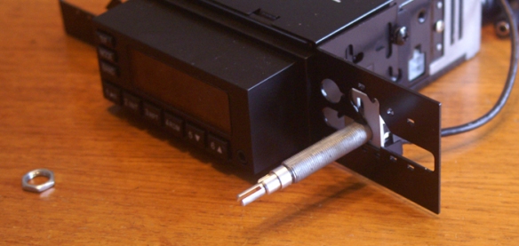
Parts for step 3: Installing the control knob shafts. Remove the rubber knob shaft covers prior to installation.

Put the control knob shafts through the retaining bracket. I never figured out if the indentations on the rectangle pieces should face towards or away from the retaining bracket but I installed them facing towards the bracket which seemed to work fine.

Place a rectangle bracket, large washer, and nut on each control knob shaft and hand tighten them so the shafts stay in place but can be moved by hand.

According to the instructions, the radio needs to be installed in the dash to make the final adjustments for the control knob shaft positions. This, I think, is for radios installed in dashboards with built-in faceplates. Buses have open rectangle slots so I used the faceplate to position the shafts. Once in their proper place, tighten the nuts installed in the previous photo.

Place a nut followed by a washer on each control knob shaft. Screw them on until they sit about halfway down the shafts.

Step 5: Time to get in the bus!! This is always my favorite part of any project. Remove the old radio or, in my case, radio block-off plate if they are present and install the radio in the slot from behind the dash. Double check the fit and position of the radio in the slot. Does it fit how you want?

It was at this point that I found the right control knob shaft bracket hit the glove compartment. I had to take the radio out and bracket off to cut it shorter but if you read step 2 carefully, you already checked for this issue.

Parts for step 6: Two small washers (not sure how four ended up in the picture) and two nuts. The I-shaped brackets with holes in the center came with the faceplate kit.

With the radio behind the dash, make sure the large washers and nuts from step 4 are still in place. Install the I-brackets, washers and nuts on each shaft. Bring the radio in the the dash slot so the I-brackets rest against the slot rim. In this photo you can see the damage to the dash incurred when a PO hacked the dash slot.

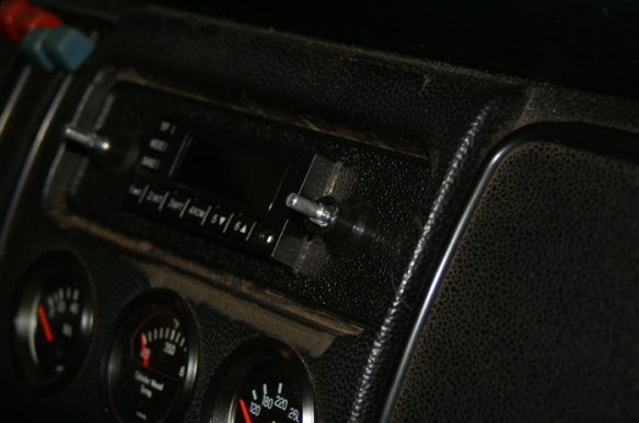
With the radio in the position outlined at the end of step 6, install the faceplate over the radio. Push it back as far as it will go and check radio position. Is the radio where you want and does it stick out of the dash adequately? Now check to make sure the rim of the dash radio slot in sandwiched tightly between the I-brackets and faceplate. Adjust the nuts behind the I-brackets (installed in step 4) until the radio is positioned appropriately. Once done, tighten the nuts on either side of the I-bracket to hold them in place. Install the faceplate followed by a washer and nut on each control knob shaft. Tighten each nut so the dash radio slot rim is sandwiched between the I-brackets and faceplate. Do not over tighten as the faceplate might crack but you want enough tension on the slot rim to hold the radio in place.

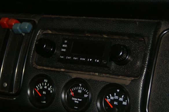
Parts for step 8: Two lower (inner) control knobs (bottom right), two upper (outer) control knobs (top right), and the two rubber control knob shaft covers removed earlier.

Install the lower control knob on the shaft. If you look closely at the shaft, you will see the top section is split parallel to the shaft. Behind this section right were the split ends, there is a slightly larger, smooth section were the lower control knob sits and turns independently of the top section (fade and balance controls). Make sure the knob is seated correctly and measure the space between the faceplate and knob.

The following is not part of the instructions and comes from memory of other radio installs. If you want the control knob shafts shielded, cut the rubber shaft covers to equal the distance you just measured from the previous photo. Measure the cover from the bottom flare.

Step 9: Time to connect power to the new fuse block. Use wire which equals the gauge of the radio wires. 18 gauge in this case.

Yellow lead is connected to a continuous power source, red to power when key is switched on, and black to ground (earth). The two blue wires are for power antennae and amplifier. I made one change to this setup by connecting both power lines to continuous power. This allows the radio to be on without the key in the ignition; a nice option if listening to music while camping. If the recommended setup is used, the ignition will need to turned to battery on (or run) position which can lead to coil and/or points damage without the engine running. One of the most frequent complaints I read about this radio concerned dead batteries if the car was not driven often. All radios draw current when the car and radio are off to keep the preset radio stations stored and is not a unique issue for this unit. A good battery should last a month or so in storage before needing to be charged but this is where removing the inline fuse (see part 1 of this series) before the car sits for a while comes in handy.

All the ground (earth) connections near the radio are occupied, so I ran the ground wire to factory ground on the headlight bucket. I only had red wire and did not want to waste time running to the store to get black wire. Good thing this wire is easy to trace after I forget why it is there!

Follow the manufacturers recommendations on fuses. I used two 15 amp fuses, one for the yellow (continuous power) lead and one for the red (ignition-on power). The instructions never mention putting a fuse on the latter lead but since I hooked it up to continuous power, I fused it anyway.

Power leads connected to the top of the fuse block and fuses installed. Continuous power on the left and ignition-on power lead on the right (since both leads are connected to continuous power in this setup, it does not really matter where they are installed on the fuse block and I only mention it here for my own future reference)

Step 10: Turn on radio. Too bad I do not have speakers setup yet, I am really curious as to how it sounds! Stay tuned for speaker installation….

Parts for step 11: Install radio back-strap. The instructions for this step are pretty good in the manual. I toyed with not installing it but in the end put it in to help stabilize the radio. Find the bolt in the center of the back of the radio. Measure the distance from the bolt to the bottom of the dash.

Using the measurement made in the previous photo, mark and then bend the radio strap into an “L” shape – the long part equaling the measurement. Working under the dash, bolt the end of the strap (left in this picture) to the back of the radio so the short end points towards the windshield. Position the short end (right) under and parallel to the dash.

Most bus owners use the speaker holes drilled in the dash when installing the strap bolt. It is easy and allows for a quick return to a nice looking dash if the radio is taken out. Insert the bolt, align the strap under the dash, add a washer and nut, and you are done.


Pingback: The sound of music – Radio install Part 3 – Preparing the front kick panels | Zero to Sixty . . .Eventually
Is there a way to wire the retro sound without the aux fuse box? I have one and can’t seem the get the wiring right in my 77 bus.
Hi Rob,
Thanks for stopping by my blog. How have you wired your radio and what types of problems are you running into? A lot of radios are wired without an aux fuse panel. Fuse #7 or #9 are the VW accessory fuses. I can’t recall if they are both continuous power, but I know #7 is and should be connected to the yellow retrosound power lead. If #9 is “keyed” power (on when key is turned) it could be used for the red lead. If #9 not keyed, use a multimeter to find another fuse to hook up the red lead. Fuses #11 or #12 might be good options. Stay away from the fuse for the wiper motor as it might cause interference with the radio when using the wipers. Ground can be tied into any bare metal surface/screw. Are you having issues getting the radio to work at all?
Hi,
Thanks so much for your “retro” article.
What I really need are the “rubber control knob shaft covers” which I call “radio shaft covers”.
I really need about 50-100 or even more for a turntable (record player) project, so if anyone has some for sale or could tell me where to get some it would be appreciated immensely.
These uniquely shaped and dimensioned shoulder washers are perfect for my repurposing and would save me much time in making my own.
Best regards,
Frank
Hi Frank,
Thanks for reading the post! I’m betting that since new radios don’t have control knob shafts any more, the shaft covers are going to be pretty hard to find. I’ve only seen them with the old style radios and this Retrosound kit. You might want to contact Retrosound directly and see if they’ll sell you what you need. Good luck!